Installer guide
DC Fast Charger Installation Guide for Electricians
DC fast charger installation guide for electricians: base, supply, cabling, earthing and commissioning, with spec-sheet input currents from 47 A to 465 A.
- Prepared by
- EVCSTAR Engineering Team
- Published
- Reading time
- 6 min
- Sources
- —
At a glance
- SC30 input current per phase (400 V)
- 47 A
- HC60 / UC60 input current per phase
- 93 A
- UC120 / CC120 input current per phase
- 186 A
- UC300 input current per phase (400 V)
- 465 A
Key takeaways
- 1Size the supply from the charger's input current per phase, not from its output kW: on EVCSTAR spec sheets that is 47 A for an SC30, 93 A for a 60 kW unit, 186 A for a 120 kW unit and 465 A for a 300 kW European UC.
- 2At 400 V three-phase, input current converts to apparent power by multiplying by 400 and by 1.732: 93 A is about 64 kVA, 186 A about 129 kVA, 465 A about 322 kVA, which is the figure to give the utility. Apply the continuous-load and diversity factors your local code requires on top.
- 3The UC and CC cabinets stand on a concrete plinth with bottom cable entry, so ducts, plinth and cable route are the first work package and must be settled before the charger arrives.
- 4Commissioning is not finished when the charger powers up: record the earthing and protection checks, the OCPP connection and a test charge on each gun, and keep the manufacturer's commissioning checklist with the file.
On this page
Short answer: a DC fast charger installation guide for electricians starts with the nameplate: get the input voltage and current per phase, design the base, ducts and supply cable for that current, earth and protect it according to your local code, then commission with documented tests and a live test session on every gun.
Start from the input current
The number that drives the electrical work is the input current per phase, because it fixes the cable, the protective device and the size of the connection. The table gives EVCSTAR spec-sheet values at the stated input voltage, with apparent power calculated as voltage × current × 1.732. They are inputs for design, not a substitute for the nameplate on the unit you receive.
| Model | Output | Input voltage | Input current per phase | Apparent power |
|---|---|---|---|---|
| SC30 | 30 kW | 400 V | 47 A | about 33 kVA |
| HC60 | 60 kW | 400 V | 93 A | about 64 kVA |
| UC60 | 60 kW | 400 V | 93 A | about 64 kVA |
| UC120 / CC120 | 120 kW | 400 V | 186 A | about 129 kVA |
| UC180 / CC180 | 180 kW | 400 V | 279 A | about 193 kVA |
| UC300 | 300 kW | 400 V | 465 A | about 322 kVA |
| UC120N | 120 kW | 480 V (North America) | 155 A | about 129 kVA |
| UC360N | 360 kW | 480 V (North America) | 465 A | about 387 kVA |
Higher voltage means lower current for the same power: a 480 V UC120N draws 155 A against 186 A for the 400 V UC120. For a multi-charger site, work out the total in the grid capacity calculator and talk to the utility about load management. In the United States the code side of this is covered in our NEC 625 guide.
Civil works and the base
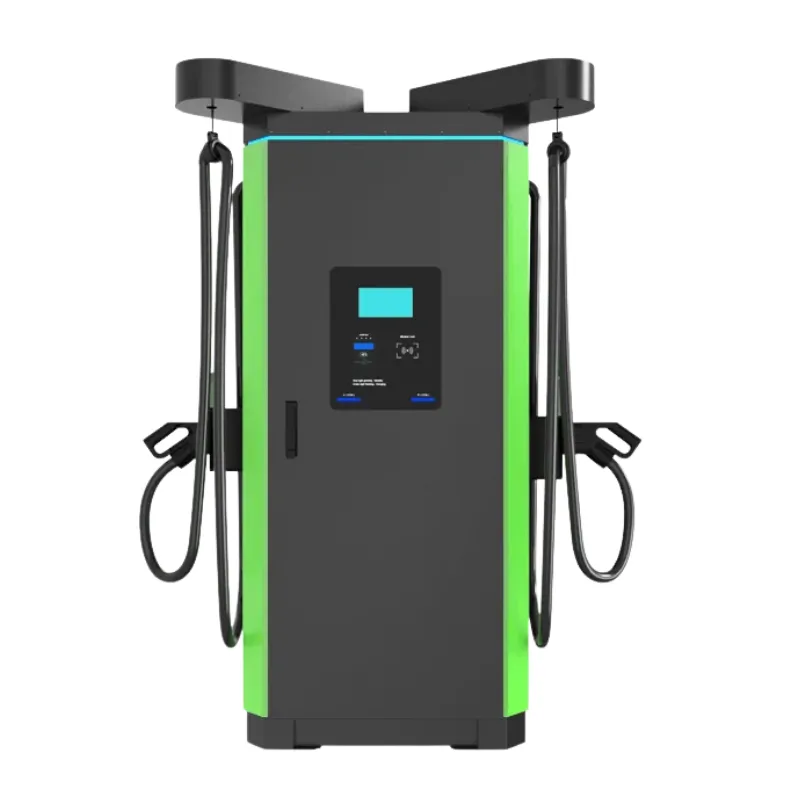
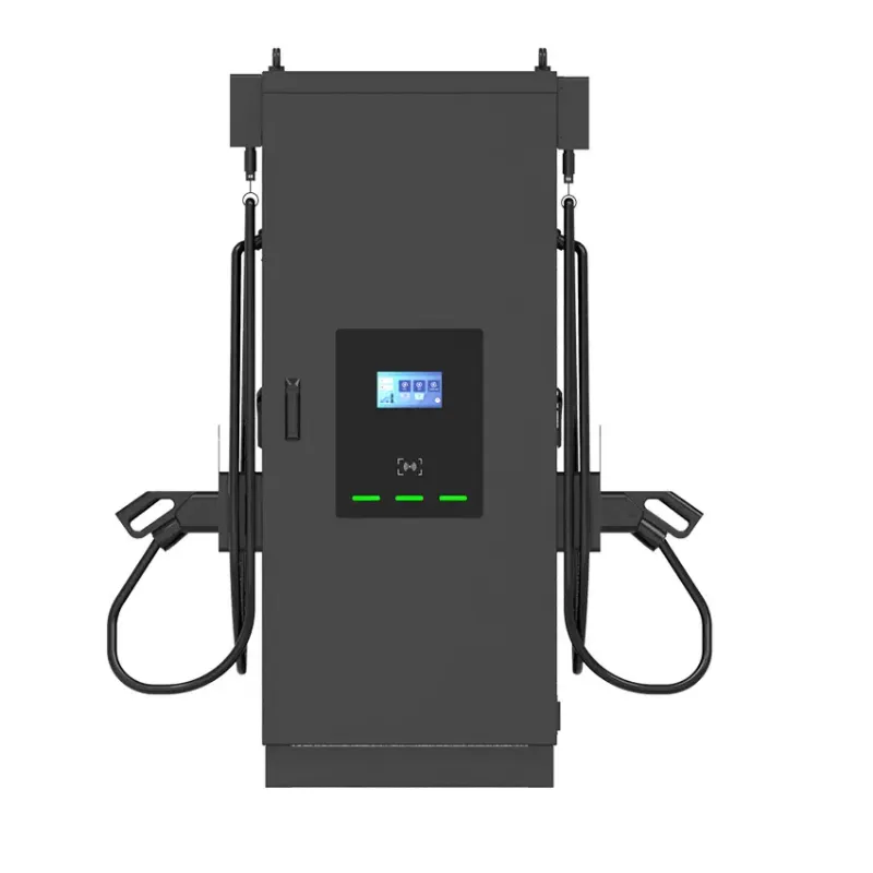
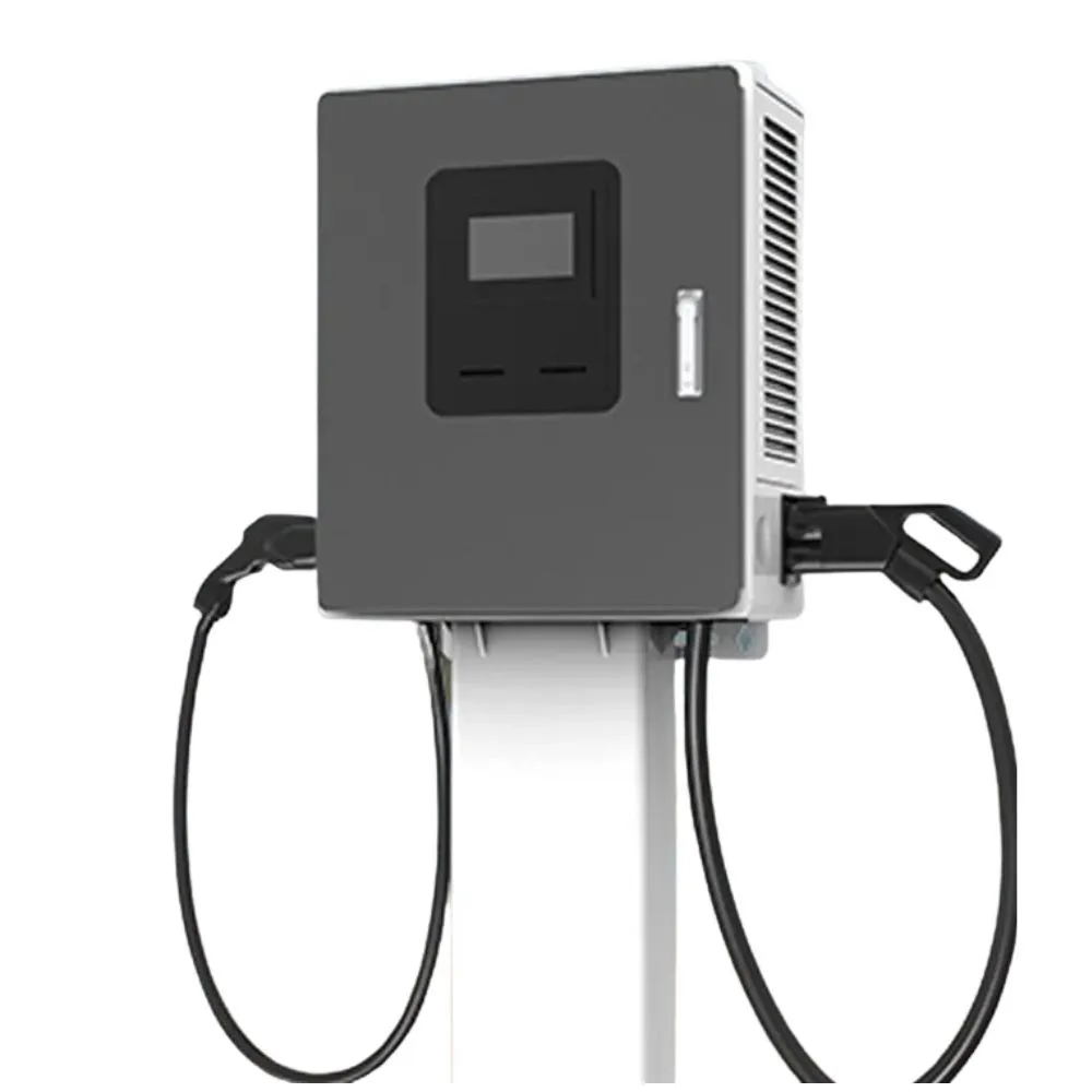
Plan the plinth, ducts and cable route before the charger is ordered, because they are on the critical path. According to the UC and CC spec sheets, these cabinets are floor-mounted on a concrete plinth with bottom cable entry, with space around the cabinet for forced-air cooling and front access for service; the UC has cable holders on both sides so one cabinet can serve two parking bays. HC units mount on a structural wall or on a pedestal, and the SC mounts on a solid wall or a pedestal, keeping the ventilation grilles clear on both sides. Ask us for the cabinet dimensions and the plinth and duct drawing for your model; the UC European cabinet is 850 × 840 × 1850 mm excluding the cable holder.
A practical civil checklist:
- Cable route and ducts from the metering point to the plinth, with draw pits where the route turns
- Plinth size and height, anchor positions and bottom cable entry per the manufacturer’s drawing
- Vehicle impact protection, drainage around the base and lighting
- Cable gland and sealing method so that the IP54 enclosure rating is not defeated
- Space for the transformer, ring main unit or metering cabinet if the utility requires them on your land
Supply cable and protection
The supply cable must carry the input current with the voltage drop and derating your code allows, and the protective device must suit the charger’s inrush and fault level. Take the current from the table, apply the code’s continuous-load factor, then the installation method and grouping derating, and check voltage drop over the real route length.
A worked example, with assumptions: a UC120 at 400 V draws 186 A per phase; the cable is copper, 95 mm² per phase, 100 m long, running at 70 °C, resistance only (no reactance), resistivity about 0.0221 Ω·mm²/m at that temperature. The resistance is about 0.00023 Ω per metre per conductor, so the three-phase voltage drop is 1.732 × 186 × 0.00023 × 100, which is about 7.5 V, or 1.9% of 400 V. Whether 95 mm² is allowed at 186 A depends on your cable table, installation method and ambient temperature; this example only shows how length and current interact. At 200 m the drop doubles. If that is too much, a larger conductor or a nearer connection point is the answer, not a lower-spec charger.
Protection choices are for the designer, but the spec sheets list the relevant options: Type B RCBO and PEN fault protection on the UC, PEN fault protection on the HC, and insulation monitoring on the SC. PEN fault protection matters where the supply neutral and earth can be combined (check which earthing system the utility provides), and RCD type must match the DC leakage the charger can produce. Confirm both with the manufacturer’s manual and your wiring code.
Earthing and bonding
Earthing is the one area where you should not follow a generic guide. The earthing arrangement (TN, TT or IT), the required earth resistance, the bonding of the cabinet and of nearby metalwork, and the treatment of outdoor installations are all set by your national code and the utility’s connection terms. Our spec sheets do not state earth-resistance targets, so the figures must come from the code and the designer. What we can say is practical: bond the cabinet as the manual instructs, test continuity back to the main earth terminal, measure the earth electrode if the system relies on one, and record the results.
Commissioning, step by step
Commissioning is a sequence you can repeat on every site, and the record is part of what you hand over.
| Step | What to do | Record |
|---|---|---|
| 1 | Visual check: terminations, torque, glands, labels | Photo and checklist |
| 2 | Earthing and bonding continuity; insulation resistance as your code requires | Test values |
| 3 | Supply voltage and phase rotation at the unit’s input | Readings |
| 4 | Power-up, emergency stop test, protection device trip test | Pass/fail |
| 5 | Network: Ethernet, 4G or Wi-Fi, OCPP 1.6J or 2.0.1 connection to the back end | Screenshot of status |
| 6 | Test charge on each gun, with a car or load bank; check power sharing on dual-gun units | Session log |
| 7 | Hand-over: manual, commissioning record, warranty details, emergency contacts | Signed sheet |
For the back-end part see our management software guide. Ask the manufacturer for the commissioning checklist for the model; we can provide ours with the technical documents for your project.
What to send us before the cabinet ships
The more you tell us about the site, the fewer surprises at the plinth. Send the supply voltage and available capacity, the cable length from the connection point, the number of guns, the connector standard (CCS1, CCS2, NACS, CHAdeMO), the earthing system and the local code through the contact page. We reply with a configuration proposal and quotation breakdown, plus the technical documents and drawings for the series that fits: SC and HC for small and mid-size sites, CC and UC for floor-standing cabinets. Installing for a client under your own name? Read what to ask for in white-label chargers too. Our warranty is 12 months.
Grid capacity calculator
- Spare power for charging
- —
- Input current per charger (400 V)
- —
- Chargers at full power
- —
Spare power = kVA × 0.95 power factor × (1 − margin) − existing peak load. Input current ≈ charger kW ÷ (√3 × 400 V), with power factor and 95 % efficiency added for DC chargers. With dynamic load management more chargers can share the same capacity at reduced power. Always confirm with your electrical engineer and the grid operator.
Frequently asked questions
- How do I size the supply for a DC fast charger?
- Start with the input current per phase on the manufacturer's spec sheet for the exact model and voltage, multiply by the line voltage and 1.732 to get kVA, then apply the continuous-load, diversity and cable-loss rules of your local wiring code. Our UC and CC spec tables list 93 A to 465 A at 400 V for 60 to 300 kW; send us your voltage and gun count and we will confirm the figures for the configuration.
- Does a DC charger need a transformer?
- It needs a three-phase supply at the input voltage on its nameplate. If the site has a different voltage or not enough capacity, a transformer or a utility upgrade is needed. The utility decides what the connection involves, so ask for its written offer before ordering equipment.
- What earthing and protection does a DC charger need?
- The requirements come from your wiring code and the manufacturer's manual, not from this page. Our UC and HC lists show PEN fault protection and a Type B RCBO as options, which matter on supply systems where the neutral and earth can be combined. Confirm the earthing system with the designer and the utility before you design the protection.
- What should be checked before the first charge?
- Visual checks of cabling, terminations and torque; earthing continuity and insulation tests to the values required by your code; correct phase rotation; the emergency stop; the network connection and a test session on each connector. Keep the results with the commissioning record.