Planning guide
DC Fast Charging Site Layout: Bays, Turning, Cable Reach
DC fast charging station layout: 4.8 x 7.2 m bays, cable reach versus cable length, bollards, canopy and queuing, with a six-bay worked example.
- Prepared by
- EVCSTAR Engineering Team
- Published
- Reading time
- 5 min
- Sources
- 3 references
At a glance
- Perpendicular bay (ZEVI 2024)
- 4.8 x 7.2 m
- Accessible stall width (BC Hydro 2021)
- 3.7 m minimum
- Bollard spacing (BC Hydro 2021)
- 1.2 to 1.7 m
- UC cabinet footprint (EVCSTAR)
- 850 x 840 mm
Key takeaways
- 1A DC fast charging station layout starts from the bay: the Irish ZEVI guidelines (May 2024) recommend 4.8 x 7.2 m per perpendicular bay including 1.2 m access zones, with the charger placed midway between two bays, outside those zones.
- 2Cable length is not cable reach: one manufacturer's site guide gives a 3.76 m reach radius for a 5.4 m standard cable, so a 6 m cable should not be assumed to reach every inlet from where the cabinet stands.
- 3Protect and light the equipment: BC Hydro (2021) suggests 1.2 to 1.7 m between bollards and 108 lux on the face of the charger out to 1.5 m, and ZEVI recommends weather protection that reaches the vehicle inlet.
- 4A six-bay site served by three dual-gun cabinets needs roughly 30 m of frontage and 7.2 m of depth in the worked example below, before queuing space, and the electrical size needs checking separately.
On this page
Short answer: a workable DC fast charging station layout gives each bay about 4.8 x 7.2 m, places the charger between two bays so both cables reach the inlets, protects the cabinet with spaced bollards, lights the face of the charger, and leaves queuing space off the public road; check cable reach with real inlet positions, not with the cable length printed on the spec sheet.
Start with the bay
The bay dimensions decide how many chargers fit on the lot, so fix them before the electrical design. The Irish ZEVI guidelines (May 2024) recommend a perpendicular charging bay of 4.8 by 7.2 m, which includes a 1.2 m access zone on both sides, in front and behind, with the zone between bay and charger widened to 1.5 m where possible and 1.5 to 1.8 m between side-by-side bays. They put a charger that serves two bays midway between them, outside the 1.2 m zone. BC Hydro (2021) suggests an accessible stall of at least 3.7 m wide, including at least 1.5 m for entering and leaving the vehicle, and stresses firm, level, paved ground and a charger pad flush with the surface; it says not to use gravel.
| Item | Recommendation | Source |
|---|---|---|
| Perpendicular bay | 4.8 x 7.2 m including 1.2 m zones | ZEVI 2024 |
| Bay to charger | 1.5 m where possible | ZEVI 2024 |
| Accessible stall | at least 3.7 m wide | BC Hydro 2021 |
| Surface | paved, on grade, not gravel | BC Hydro 2021 |
Pull-in, between-bays or pull-through
The layout type is a trade-off between land, vehicle types and kerb work. BC Hydro describes three arrangements. In a pull-in layout with chargers at the head of the stalls, kerbs usually need a roll-over or flush section so drivers can reach the equipment. Chargers placed between stalls suit a surface lot and, with four stalls, can create a fully accessible station without kerb changes. A pull-through lane suits larger vehicles and trailers, as at a fuel station, and the driver chooses the side nearest the inlet; it needs the most land. For a fleet with vans or trucks, plan the turning path first and add the bays around it; the fleet capacity guide covers how many bays that takes.
Cable reach is not cable length
The cable length on a spec sheet is longer than the distance the cable can actually cover on a car. ChargePoint’s site guide for its DC unit gives a reach from the station to the charge port of about 3.76 m (12 ft 4 in) at 0.6 m above ground for its 5.4 m standard cable, and about 5.49 m (18 ft) for its 7.6 m cable with a longer management system. It tells designers to place the station to maximise reach across different inlet positions. ZEVI says a tethered cable should reach any vehicle parked with its inlet as close as possible, recommends overhead cable management on all fast chargers, and cites a PAS 1899 limit of 7.5 m on cable length. Cable management also keeps the connector off the ground, which BC Hydro calls a tripping and damage risk.
Protection, lighting, weather and signs
Four details are cheap to include at design stage and expensive to retrofit.
- Bollards: BC Hydro suggests 1.2 to 1.7 m between bollards, bright and reflective, to protect the charger yet leave a path for wheelchairs. ZEVI cites PAS 1899 for bollards of at most 0.1 m diameter, at least 1 m high, spaced at least 1.4 m between centres and within 0.3 m of the charger.
- Lighting: BC Hydro’s minimum is 108 lux on the face of the charger out to 1.5 m, then 32 lux out to 18 m, and 32 lux behind and beside it.
- Weather and roof: ZEVI wants protection that covers the charger up to the inlet; BC Hydro asks for roof clearance, or a roof that opens, so a crane can lift chargers in and out.
- Queuing: ZEVI says to include a designated queuing area with clear signage where needed, so waiting cars do not block the access road. Size it from your busy-hour arrivals, not from the number of bays.
A six-bay worked example
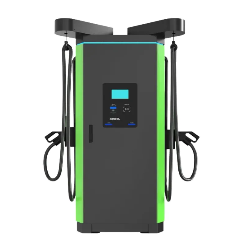
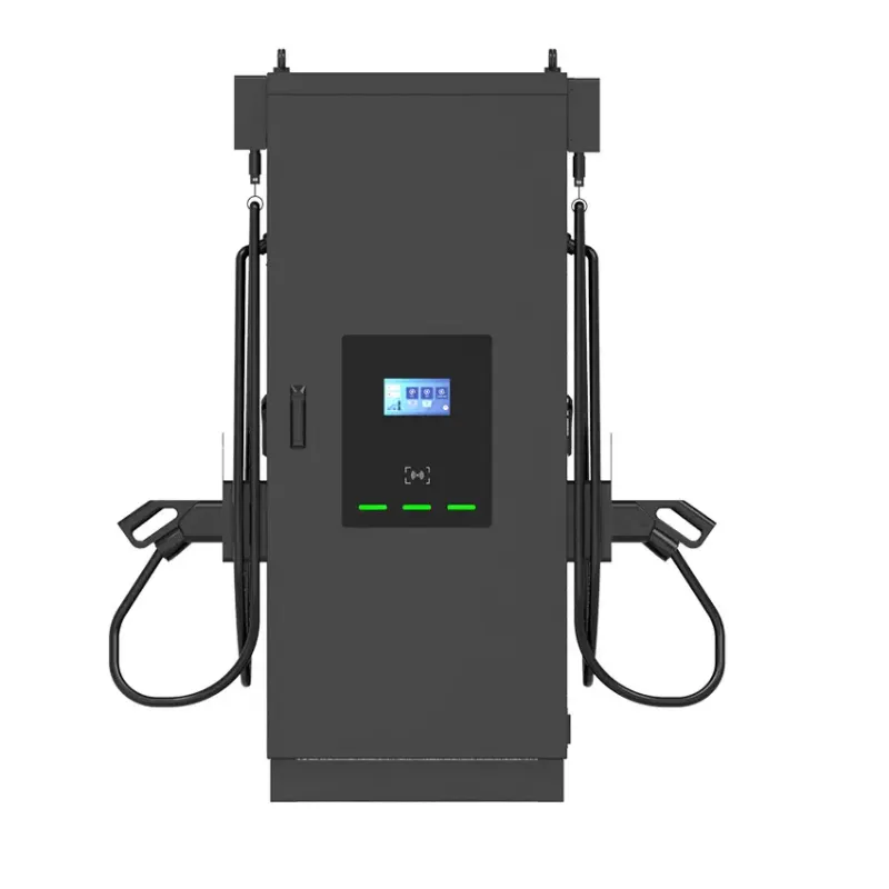
Take three dual-gun cabinets, each between two perpendicular bays, using the ZEVI zones. The EVCSTAR UC series cabinet is 850 mm wide, 840 mm deep and 1,850 mm high, excluding a 115 mm cable holder, with 6 m cables and holders on both sides so one cabinet serves two bays. The figures that follow are our arithmetic from those dimensions and the guideline zones, not a drawing.
| Step | Calculation | Result |
|---|---|---|
| One pair, across | 2.4 m car zone + 1.2 m access + 0.85 m cabinet + 1.2 m access + 2.4 m car zone | 8.05 m |
| Three pairs plus gaps | 3 x 8.05 + 2 x 1.8 m between pairs + 2 x 1.2 m ends | 30.15 m |
| Depth | ZEVI bay length, including 1.2 m front and rear zones | 7.2 m |
| Reach, near-side inlet | cabinet at mid-depth: sqrt(1.2² + 2.4²) | 2.7 m |
| Reach, far-side inlet | sqrt(3.6² + 2.4²) | 4.3 m |
| Rule-of-thumb reach for a 6 m cable | 6 x (3.76 / 5.4), using ChargePoint’s ratio | about 4.2 m |
The far-side inlet at 4.3 m is borderline against the 4.2 m rule-of-thumb figure, which is why cabinets should sit at mid-depth and why a driver may have to park on the side of the bay that suits their inlet. Confirm the real reach with us for your holder position before fixing the plinth.
Electrically, a 300 kW European-build UC cabinet draws 465 A per phase at 400 V (spec sheet), about 322 kVA by the usual three-phase formula; three cabinets are about 966 kVA at full output, which is a transformer step. Power sharing and site limits change that, so run the numbers in the grid capacity calculator and read the transformer cost guide.
Planning the layout with EVCSTAR equipment
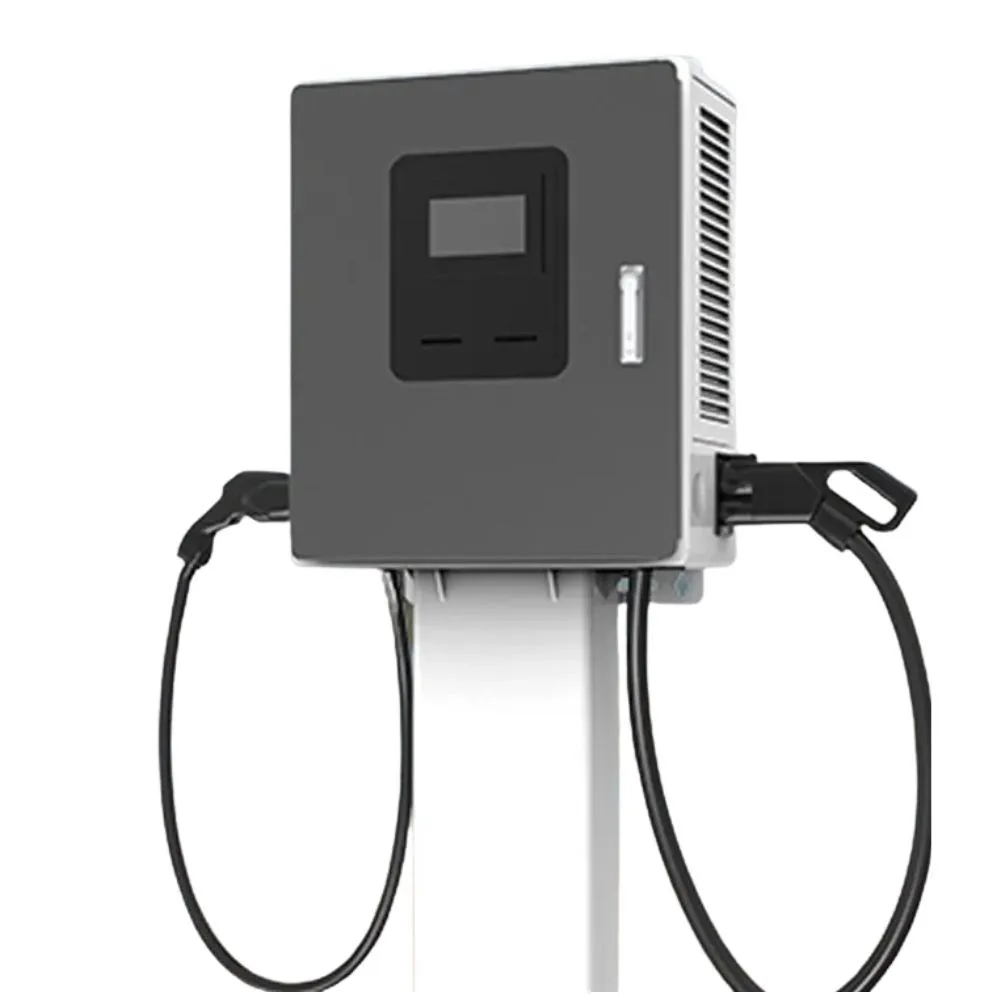
Choose the cabinet by the lot you have. The UC series serves two bays from one 850 x 840 mm cabinet; the CC series is 700 x 500 x 1,700 mm with 5 m cables for tighter bay ends; the HC series is 690 x 300 mm in plan on a wall or pedestal when land is short. The spec sheets list a concrete plinth with bottom cable entry for the floor-standing units; the plinth size and clearances are confirmed per order.
Send a plan of the lot (bay count, frontage and depth, vehicle types, available kVA and where the transformer sits) through the contact page, and we will reply with a configuration proposal and quotation breakdown, including the plinth and holder positions for your layout. For choosing the site itself, read best location for an EV charging station.
Grid capacity calculator
- Spare power for charging
- —
- Input current per charger (400 V)
- —
- Chargers at full power
- —
Spare power = kVA × 0.95 power factor × (1 − margin) − existing peak load. Input current ≈ charger kW ÷ (√3 × 400 V), with power factor and 95 % efficiency added for DC chargers. With dynamic load management more chargers can share the same capacity at reduced power. Always confirm with your electrical engineer and the grid operator.
Frequently asked questions
- How big is one DC fast charging bay?
- For a standard perpendicular bay the ZEVI guidelines recommend 4.8 x 7.2 m including a 1.2 m access zone on both sides, in front and behind, with 1.5 m between the bay and the charger where possible. BC Hydro suggests an accessible stall at least 3.7 m wide where space allows. Local codes can require more, so check them first.
- Do I need a pull-through layout?
- Only if your customers include trucks, vans with trailers or vehicles with a charging inlet at either end. BC Hydro describes pull-through as a good option when the site has room, because drivers can park on the side nearest the inlet. It uses more land than pull-in layouts, so check the lot before you commit.
- Why does a 6 m cable not reach every car?
- Because the cable runs along an arc, down to the holster and around the car, not in a straight line. ChargePoint's site guide, for example, gives a 3.76 m reach radius for a 5.4 m standard cable. The reach of a specific EVCSTAR cabinet depends on holder position and cable management, so confirm it for the layout.
- Should a DC charging site have a canopy?
- It is optional but recommended where weather matters. ZEVI says protection should cover the charger up to the vehicle inlet; BC Hydro adds that the roof should leave clearance, or open, so chargers can be craned in and out. Keep the canopy columns outside the access zones.
References
- [1]Universal Design Guidelines for Electric Vehicle Charging Infrastructure (May 2024), section 6.2. Zero Emission Vehicles Ireland (ZEVI).
- [2]EV Fast Charging Design and Operational Guidelines for Public DCFC Stations in British Columbia, version 1.1 (March 2021). BC Hydro and Powertech Labs.
- [3]Site Design Guide for Standalone and Paired Stations, DC Fast Charging Station Express 280. ChargePoint.